


INTRODUCTION
The guidewire is a cornerstone accessory in endoscopic retrograde cholangiopancreatography (ERCP). A guidewire helps achieve selective cannulation and traversal of irregular strictures in the bile and pancreatic ducts and supports accessory placement or insertion during various ERCP procedures [1,2]. Several reports have suggested that proper selection of a guidewire could increase the success rate of selective cannulation, and that the wire-guided cannulation technique could be superior to the contrast-guided cannulation technique in increasing the primary bile duct cannulation rate and reducing the incidence of post-ERCP pancreatitis [3-9].
The guidewire was originally developed to maintain access to common bile duct (CBD) during therapeutic procedures, but it is currently used to facilitate selective deep cannulation of CBD and to pass severe strictures. Manufacturers have also continued to introduce better functions for guidewires. Many varieties of guidewire are available in Korea, and their choice depends on the preference of the operator, the type of procedure, and the status and location of the disease. Also, guidewires from different manufacturers have different features; their performance depends on various basic features, such as thickness, tip shape, flexibility, stiffness, and hydrophilic coating [1,2]. Therefore, it is very difficult to distinguish performance abilities for diverse guidewires. It is also not easy to conduct prospective clinical studies that evaluate guidewires in specific situations, such as difficult cannulation, wire-guided cannulation, and hilar cholangiocarcinoma. Moreover, even if prospective clinical studies had progressed well, it is unreasonable to apply their results uniformly to all situations.
We conducted this technical study to introduce general details of currently available guidewires, investigate the characteristics of each guidewire type, and evaluate the efficiency and rapidity of insertion.
MATERIALS AND METHODS
General details of the guidewires [1,2]
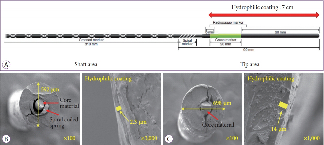
Guidewires for ERCP are morphologically divided into two parts: a stiff shaft for supporting or guiding the passage of various accessories, and a hydrophilic flexible tip area for tracking and entering desired routes. Guidewires are structurally classified into monofilament wires, coiled wires, and coated or sheathed wires. Most of the ERCP guidewires used in recent years have had a monofilament core made of stainless steel, nitinol, or a shape-memory alloy, and an outer sheath coated with Teflon, polyurethane, or other polymers to reduce surface friction. A spiral-coiled spring is a covered monofilament core at the tip area of some guidewires that confers solidity and high flexibility, which improves traceability (Fig. 1). The length of a guidewire ranges from 150 to 650 cm, but guidewires of around 450 cm are commonly used. The thickness of a guidewire ranges from 0.46 to 0.97 mm (0.018 to 0.038 inch). Although the thinner guidewire is less stiff, the 0.025-inch guidewire with improved flexibility has been widely used.
According to the various factors and types described above, each guidewire has different characteristics. Therefore selection of a guidewire depends on the clinical situation, the preference of the operator, and the presence of assistance.
Basic characteristics of guidewires used in this study
The guidewires used in this technical study are mainly ones currently used in Korea; their basic characteristics are shown in Table 1. These include: Fusion Loop TipTM (0.035-inch diameter, 205-cm length, loop-shaped tip; Cook Endoscopy, Winston-Salem, NC, USA); gSliderTM (0.035-inch diameter, 450-cm length, straight tip; Medwork GmbH, Aisch, Germany); VisiGlide 2TM (0.025-inch diameter, 450-cm length, angled tip; Olympus Co., Tokyo, Japan); Tracer Metro Direct 35TM (0.035-inch diameter, 480-cm length, curved tip; Cook Endoscopy); Tracer Metro Direct 25TM (0.025-inch diameter, 480-cm length, curved tip; Cook Endoscopy); OptimosTM (0.035-inch diameter, 450-cm length, straight tip; Taewoong Medical, Gimpo, Korea); JagwireTM (0.035-inch diameter, 450-cm length, straight tip; Boston Scientific, Marlborough, MA, USA); DreamwireTM (0.035-inch diameter, 450-cm length, straight tip; Boston Scientific); Acrobat IITM (0.035-inch diameter, 450-cm length, curved tip; Cook Endoscopy).
Basic property tests
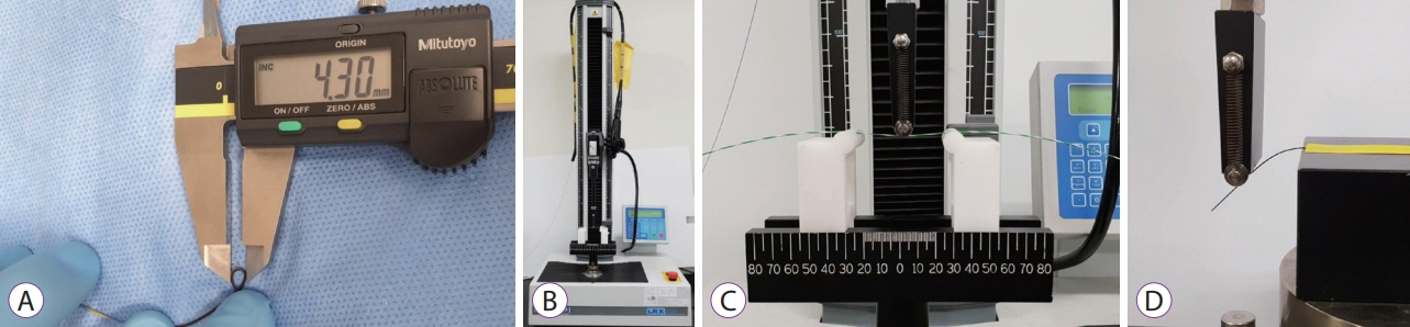
The basic configuration is similar for most of the selected guidewires, but because there are some differences, several of the known basic features were measured again. We measured the width of the tip and shaft of the guidewires using a micrometer (IP 65; Mitutoyo Co., Kawasaki, Japan). Using a digimatic caliper (CD15ADX; Mitutoyo Co.), we also measured the tip length of the guidewires, and the minimum width of the loop when the tip of the guidewire was bent as far as possible until there was no deformation (Fig. 2A). We measured the minimum width of the loop of the tip because flexible and small knuckling formation of the tip can be very helpful when inserting a guidewire, and could influence operator preference for guidewires. We used a universal testing machine (LRX plus; LLOYD Instrument Ltd., West Sussex, England) to conduct the three-point bending test to measure the flexibility and the change in the stiffness of the shaft as it bends (Fig. 2B, C). The distance between two points fixing the guidewire was set to 60 mm, and the maximum depth of bending was set to 30 mm. The bending test could not be applied to the tip of the guidewire because of the uncheckable and extremely low bending force by this machine (Fig. 2D). We performed all property tests twice for two of the same guidewires and averaged the four measurements.
In vitro test using 3D-printed silicone tubes
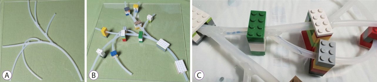
We made and used two different in vitro models for evaluating the success rate and insertion time of each guidewire. To make various stricture models, we fabricated ten silicone tubes using silicone molding techniques with 3D printing (Fig. 3A, B). The negative molders were 3D printed (3DM DW-06; 3DMaterials, Daejeon, Korea, Zeron-2500; Zeron, Seoul, Korea), and then injection molding was used to obtain silicone tubes in translucent silicone material. The length of each silicone tube was 30 cm, the diameter of each hole was 4 mm, and the diameter of a wider hole was 8 mm.
Ten skilled ERCP staff members participated in this technical study. The ten participants included five ERCP endoscopists and five ERCP assisting nurses who had carried out more than 1,000 ERCP procedures prior to the study. We tried to minimize surface friction and hydrophilic condition by replenishing the saline in all tubes before each test, or when replacing the operator. A guidewire was inserted into each silicone tube through a cannulation catheter (ERCP-catheterTM; MTW-Endoskopie, Wesel, Germany) (Fig. 3C). We measured the total insertion time and the number of successes for each guidewire (Fig. 3D).
In vitro test using a hand-made biliary tree silicone model
To make a biliary tree silicone model, we used two types of commercial silicone tubes (inner diameters 5 and 7 mm). Six small-diameter silicone tubes were attached diagonally to a large-diameter silicone tube with a bond, so that it could be divided into six branches to represent the biliary tree (Fig. 4A). Then, we attached the assembled silicone tube to a 40├Ś40-cm-wide transparent board using Lego blocks to form the three-dimensional shape (Fig. 4B). Because the tubes were passed through the Lego blocks, the tree was not fully fixed and was flexible enough to show flexibility during the guidewire insertion test.
As with our in vitro test using 3D-printed silicone tubes, we tried to minimize surface friction and hydrophilic condition by replenishing the saline in all branches before each test, or when replacing the operator. A guidewire was inserted through a bowing catheter (Swing TipTM; Olympus Co.) for selective insertion. When the assistant inserted the guidewire through a catheter to each branch of the silicone model, the operator facilitated insertion of a guidewire into each branch by adjusting the bowing angle of the bowing catheter. We measured the total insertion time and the number of successes for the six branches for each guidewire (Fig. 4C).
Statistical analysis
We used KruskalŌĆōWallis one-way analysis of variance (non-parametric) to analyze the difference of total insertion time and success rate. p<0.05 was considered statistically significant. For the statistical analysis, we used IBM┬« SPSS┬« Statistics Version 21.0.0 (SPSS Inc., Chicago, IL, USA).
RESULTS
The results of basic property tests
The results of the basic technical tests are summarized in Table 2. The minimum values of the loop formation showed different results even if tip thicknesses was similar, suggesting different results for guidewire insertion through knuckling. One (VisiGlide 2TM; Olympus Co.) of the 0.025-inch guidewires showed better loop formation than other guidewires due to its thinner and flexible coiled spring at the tip.
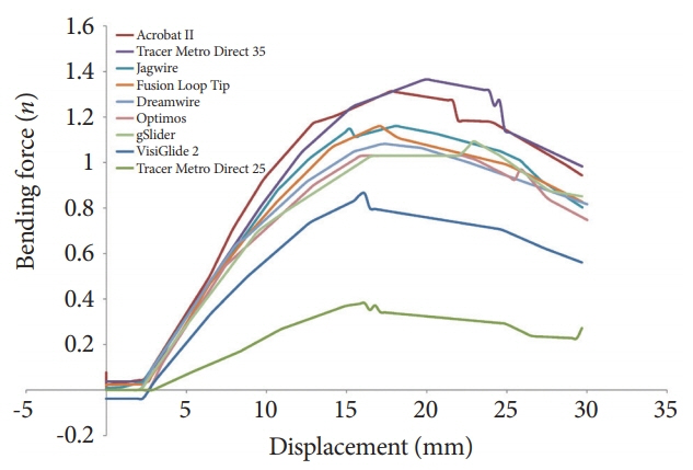
The three-point bending test showed the maximum bending force and the maximum bending stiffness. For example, one guidewire showed relatively high bending stiffness even though the shaft thickness was relatively small. In contrast, another guidewire showed relatively low bending stiffness even though the shaft thickness was similar. One (Acrobat II TM; Cook Endoscopy) of the 0.035-inch guidewires showed the highest bending force and bending stiffness. The change in the bending force according to the displacement of the bending point is shown in Fig. 5. In most of the guidewires, the slope of the bending force increased sharply in the early stage and then was steadily maintained, even if the bending became severe. Typically, one (VisiGlide 2 TM; Olympus Co.) of the 0.025-inch guidewires showed a change relatively similar to that of the other 0.035-inch guidewires.
In vitro testing results
The results of the in vitro tests using 3D-printed silicone tubes are summarized in Tables 3-5. Of the ten silicone tubes, all guidewires passed through nine tubes, although the times were different. However, since the insertion rate was significantly different in one tube with severe stricture (Fig. 3D), we placed this tube as the last of the ten tubes, and then measured total insertion time and frequency of insertion. The success rate and the total insertion time were better for guidewires with resilient shafts and highly flexible and angled tips than for other types of guidewires (p<0.001). The thickness of the guidewires did not affect the total insertion time (p=0.390) or the success rate (p=0.099).
The results of the in vitro tests using a biliary tree silicone model are also summarized in Tables 3-5. Of the six branches, all guidewires passed through the five branches, although the times were different. However, since the insertion rate was significantly different in one branch (the right posterior branch) (Fig. 4C), the branch was placed last in the test. The success rate and the total insertion times were better for guidewires with resilient shafts and highly flexible and angled tips than for other types of guidewires (p<0.001). Although the thickness of guidewires affected the success rate (p=0.001), it did not affect the total insertion time (p=0.256).
DISCUSSION
In general, when we use new endoscopic accessories, we rely on the companyŌĆÖs official marketing report and marketing strategy to understand the product when it is launched. However, operators are exposed to the actual pros and cons of the product while using them for patients and often feel that there are some difference from the official report of the company. A product can also feel different depending on the operatorŌĆÖs technique and product preference. In this technical study, we tried to explain this gap more systematically. There are many limitations to conducting clinical studies with the purpose of obtaining an objective understanding of new product characteristics. Specifically, very expensive research costs, achieving similar patient conditions, and accounting for simultaneous use of different accessories are the biggest constraints. Rather than attempt to gauge which products are better, or what features a product may have, a technical study seeks to understand the reasons behind these product characteristics.
We conducted this study in order to elucidate the basic structure, basic properties, and materials used for currently available guidewires in Korea. In addition, we investigated the guidewiresŌĆÖ technical characteristics, focusing on their efficiency and speed of insertion. During this study, two problems presented a great burden to researchers. First, we could not compare the advantages and disadvantages of all guidewires, therefore we decided to compare only the insertion time and selective cannulation rate. Second, we were challenged in finding ideal tools to measure the guidewires objectively. We also had spent a great deal of time finding new methods that had not been reported previously. We thought that the most suitable material for in vitro testing would be a silicone tube. A commercial silicone tube is simple, straight, and cylindrical with a constant diameter, and could be used in an in vitro model. Therefore, we used 3D printing to produce silicone tubes in the special shapes we wanted (Fig. 3). We were able to use the running direction, or the inner diameter of the lumen. However, unlike a commercial silicone tube, the silicone used in 3D printing is harder to use because it is transparent, and once formed in a biliary tree shape, it becomes too hard, and cannot be used in a technical study. Therefore, 3D-printed silicone tube models had to be made in straight shapes in order to carry out the technical study. At the same time, a separate model with a curved biliary tree was required to compare the selective cannulation ability of the guidewires. Therefore, we used simply-shaped and commercially-sold silicone tubes to make an in vitro biliary tree model. The tubes were attached to each other using a silicone bond (Fig. 4). This model could not be applied to different strictures, but it could be made stereoscopic and semi-movable using Lego blocks, and the direction of the branches could be set as desired, which allowed it to be shaped like an actual biliary tree. This allowed us to test selective cannulation.
Tables 1 and 2 summarize the basic features of the guidewires used in this study and show that they have similar structures but very different configurations and technical properties. These fundamental differences are the result of trying to make the most ideal product through numerous in vitro and in vivo tests, which are unique to each company. However, from the point of view of selection, these features could not decide which guidewire to use. To further objectively measure this, we used two in vitro models to test the insertion time and selective cannulation rate. As mentioned in the results, Tables 3, 4, and 5 show different results for each guidewire. In terms of shaft thickness, there were no significant differences in the insertion time, but thin guidewires showed some better results in the frequency of insertion. However, in considering the bending force of the shaft, we found that a thin guidewire with a relatively high bending force tended to overcome all other parameters. Therefore, the shaft must be elastic to ensure forward axial transmission of forces [1]. In terms of the shape of the tip, the angled shape was more effective for selectivity, and it also had some effects on time. Coincidentally, we think that the recently released products with a spiral-coiled spring at the tip were superior in all respects. The most important part of the guidewire configuration for biliary cannulation is the tip, and the new products are mainly focused on this part [10,11]. However, in order to ensure an objective evaluation, we believe that the research method should be more elaborate. More accurate results could be obtained if the research were conducted separately for each tipŌĆÖs core material, coating, and shape, even for the same products.
The limitations of this study are as follows: (1) The testing environment was very different from a human body, since we relied on in vitro models and (2) Because of the limited testing environments, we could not perform the test on diverse kinds of guidewire. Indeed, even the same product could not be divided according to the shape of the tip. The greater the number of products used, the more difficult statistical analyses would become. (3) More skilled operators were unable to repeat the test more often. (4) Although we repeated the saline flushing due to the severe friction of the silicone tube, there were significant limitations to this approach. Filling the silicone tube with glycerin could have greatly reduced friction, but we did not do so, because we wanted to test the hydrophilic properties of the guidewires. (5) We could not investigate the tip bending force with a more sensitive measuring instrument, which could have provided information on the special features of spiral coiled springs at the tip area. Despite these limitations, to the best of our knowledge, our study is the first attempt at a technical study of guidewires. As mentioned earlier, we hope that this study will help readers to understand what features will bring out the benefits of guidewires, rather than gauge which guidewire is better.
In conclusion, among several types of guidewires, some factors (highly flexible and angled tip, and resilient shaft) could be associated with the efficiency and rapidity of the guidewire insertion.