Evaluation of the mechanical properties of current biliary self-expandable metallic stents: axial and radial force, and axial force zero border
Article information
Abstract
Background/Aims
Mechanical properties (MPs) and axial and radial force (AF and RF) may influence the efficacy and complications of self-expandable metallic stent (SEMS) placement. We measured the MPs of various SEMSs and examined their influence on the SEMS clinical ability.
Methods
We evaluated the MPs of 29 types of 10-mm SEMSs. RF was measured using a conventional measurement device. AF was measured using the conventional and new methods, and the correlation between the methods was evaluated.
Results
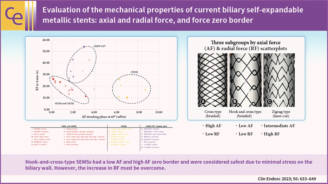
A high correlation in AFs was observed, as measured by the new and conventional manual methods. AF and RF scatterplots divided the SEMSs into three subgroups according to structure: hook-and-cross-type (low AF and RF), cross-type (high AF and low RF), and laser-cut-type (intermediate AF and high RF). The hook-and-cross-type had the largest axial force zero border (>20°), followed by the laser-cut and cross types.
Conclusions
MPs were related to stent structure. Hook-and-cross-type SEMSs had a low AF and high axial force zero border and were considered safest because they caused minimal stress on the biliary wall. However, the increase in RF must be overcome.
INTRODUCTION
Self-expandable metallic stents (SEMSs) are commonly used for the treatment of malignant biliary strictures.1-3 Biliary SEMS can be divided into zigzag, cross, and hook types, and they are manufactured using two fabrication methods (laser-cut or braided).4 The zigzag stent consists of a wavy wire formed into vertically connected rings comprising cylinders.5,6 The laser-cut stent is based on the zigzag stent and classified according to their shape, number of cells and how they are connected. In contrast, braided stents are classified based on the braid-pattern, cell size, and wire knit thickness. There are two types of braided stents: cross-knit and hook-and-cross-knit (Fig. 1).
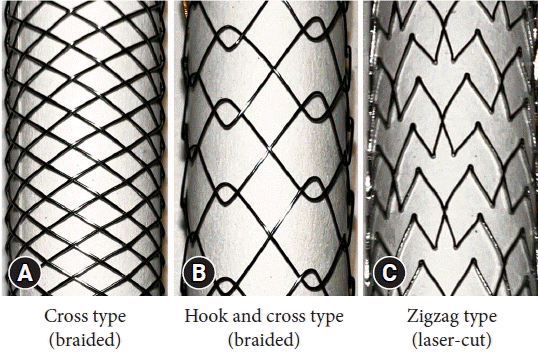
Types of biliary self-expandable metallic stents. (A) Cross-type stents are knitted to form an X-shape, and the wires do not separate (WallFlex). (B) Hook-and-cross-type stents are formed by hook and cross knitting, in varying proportions. In hook knitting, the wires form a V-shape, and are separated from each other by bends (Hanaro). (C) Zigzag-type stents consist of a wavy wire shaped into vertically connected rings forming a cylinder. The laser-cut stent is based on the zigzag stent (EPIC).
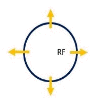
The mechanical properties (MP) of metallic stents vary depending on their structure, wire thickness, and cover material.7 Several MP affect the clinical efficacy of SEMS, and the US FDA has published parameters to be measured for clinical application8: (1) dimensional verification; (2) foreshortening; (3) recoil of balloon-expandable stents; (4) stent integrity; (5) radial compression force; (6) radial outward force; and (7) radiopacity. In addition to radial compression and outward force, we measured the axial force (AF) and classified the SEMS into three groups.9 AF is the straightening force on the central axis of the stent, and radial force (RF) is the expanding force that induces radial deformation of the stent (Table 1). AF contributes to the conformability of the bile duct, and RF contributes to its dilation. AF and RF are closely associated with biliary stent function and the incidence of adverse events.10,11 A strong AF can cause acute cholecystitis12,13 and post-endoscopic retrograde cholangiopancreatography pancreatitis.14,15 A weak RF is associated with stent dislocation.16
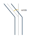
Some SEMSs can maintain a bend at various angles; hook-and-cross-type SEMS can have large angles. We investigated the AF strength and the angle at which the force is relieved to return the SEMS to a straight position; this was referred to as the axial force zero border (AFZB) (Table 1). We propose the use of AFZB to analyze the relationship between clinical outcomes and stent MP. SEMSs with a large AFZB are considered to exert low stress on the bile duct, and thus, may have a low complication rate. In this study, we measured the AF, RF, and AFZB of the main stents currently used in clinical practice and classified them according to their characteristics to evaluate the relationship between stent characteristics and clinical efficacy.
METHODS
Types of biliary SEMSs
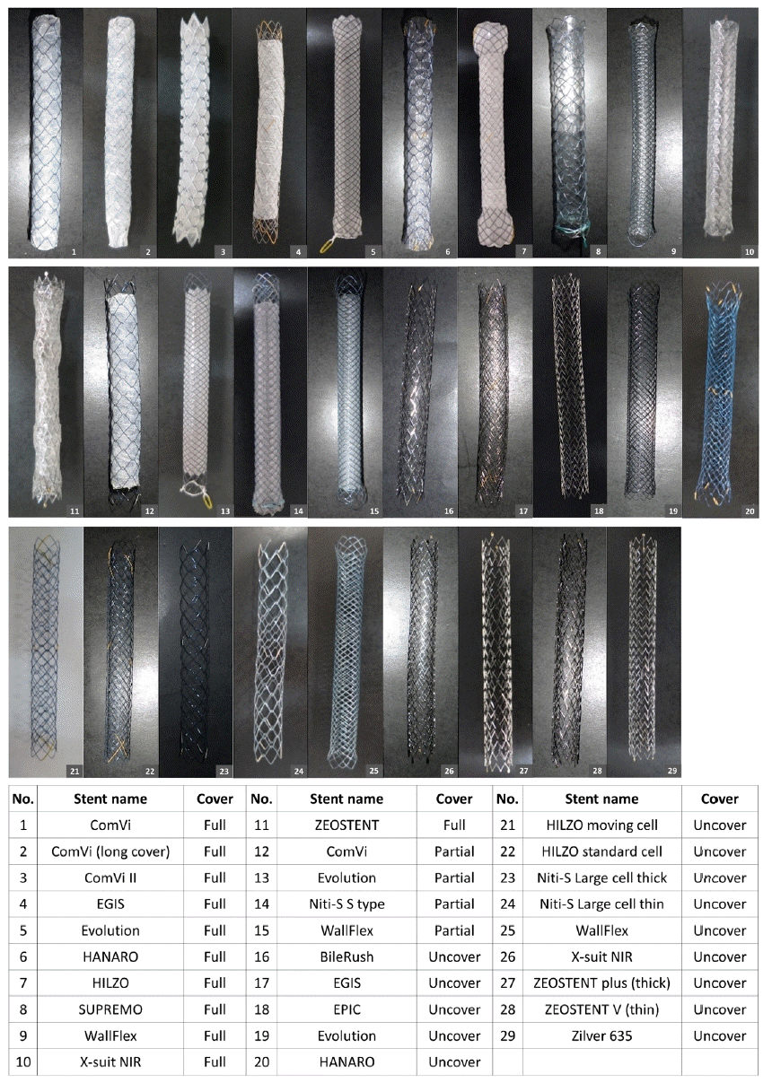
The MP of 29 different biliary SEMSs were evaluated. Two stents of each type (58 SEMS) were assessed by five physicians (T.F., T.S., R.I., S.Y., and H.I.; Fig. 2). Two engineers (H.S. and C.G.) instructed the physicians on how to measure the RF and AF. The mean measurements for each stent type and size were used in the analysis.
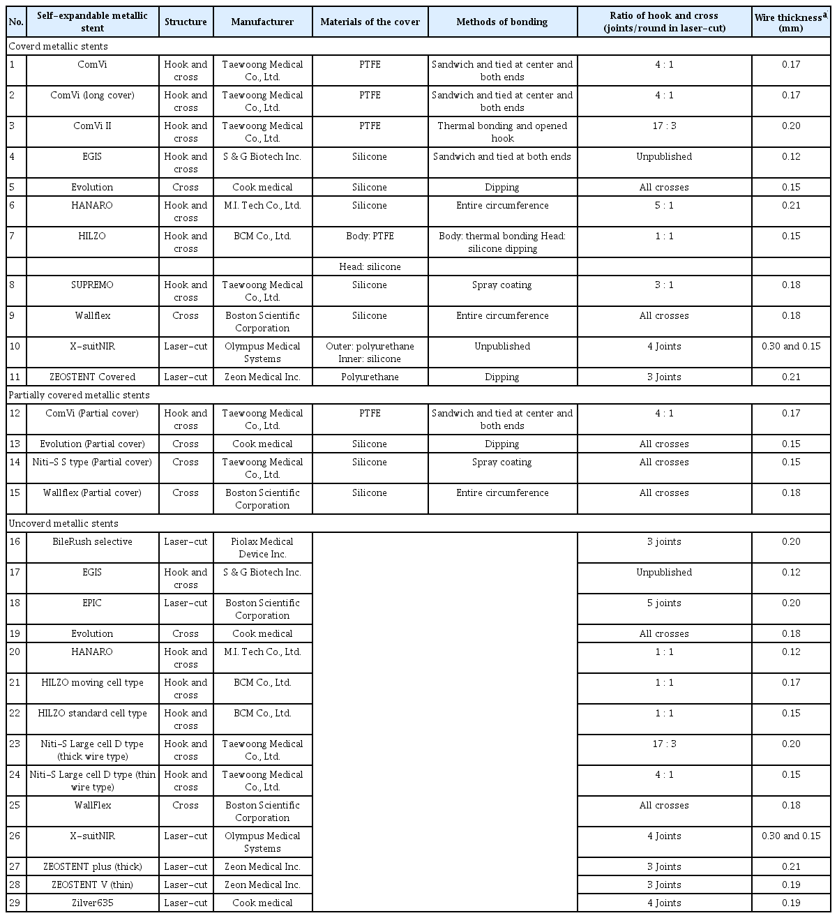
SEMSs (8 cm in length and 10 mm in diameter) assessed in this study were: 11 covered, four partially covered, and 14 uncovered (Table 2). The stents varied in terms of hook-to-cross ratios, wire thicknesses, cover materials, and covering methods. The SEMSs were divided based on the manufacturing method (21 braided and eight laser-cut). The braided SEMSs were further divided based on the knitting method (seven cross-only and 14 hook-and-cross hybrids).
Measurement of radial force
RF was measured as described by Sasaki et al.,17 using an RF measurement device (Model TTR2; Blockwise Engineering LLC; Fig. 3). The measurement was started at 3 mm for the 10-mm-diameter stents in the expansion phase. The stent was compressed from the outside to a cylinder diameter of 4 mm. A force gauge inside the cylinder continuously recorded the outward RF during the stent expansion phase. The compression RF was the force required during the compression phase. The outward RF dilates the stricture after stent placement, whereas, the compression RF counteracts tumor growth and bile duct narrowing after stent expansion.
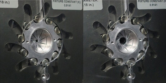
Radial force measurement device. The stent samples were inserted into the cylinder and then expanded. Expansion and resistance forces were measured.
The RF measurement device provided a hoop force (HF) value, as reported previously.9 RF was calculated using the following formula17: RF=HF×2π. The RF versus stent diameter curves were plotted using the average value of each stent type (Fig. 4).
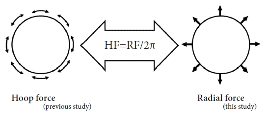
Relationship between hoop force (HF) and radial force. The HF was modified to accord with the original concept of radial force. Radial force was calculated by multiplying HF by 2π (6.28). RF, radial force.
We set the typical RF value to 4 mm when comparing the characteristics of the stents, in line with a previous study; 4 mm is considered to be approximately half the typical stent diameter and the minimum required for successful biliary drainage.
Measurement of axial force
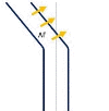
The AF was measured in two ways. In the conventional measurement method, as reported by Isayama et al.,9 the SEMS was fixed in a vise, and AF was measured manually using a force gauge (DPX-0.5; Imada Co. Ltd.) while maintaining the SEMS angle at 60° (Fig. 5A).

(A) Conventional manual method of measuring axial force (AF). This method measures the linearizing force of self-expandable metallic stent bending at 60°. (B) New AF measurement method. This method automatically measures torque in a straight stent position using an AF measurement device.
The second method, which is new, uses a custom-made AF measurement device (i-Course Co., Ltd.; Fig. 5B). The SEMS was placed in a jig in the neutral position, and the shaft rod was rotated to 90° at a rotation speed of 10°/s (bending phase). After a two seconds interval, the shaft rod was returned to the neutral position at the same speed (straightening phase). In both methods, data were measured three times per stent to increase accuracy, and the average values were obtained. The force during the bending phase is called the resistance AF, and the force required during the straightening phase is called the straightening AF. Although the clinical significance of the resistance AF is unclear, the straightening AF, acts against the bile duct wall and duodenal papilla after stent placement and seems to be related to the onset of various stent-related complications.
The straightening AF at 60° using the new measurement method was compared to that obtained using the conventional manual method; these forces were then correlated. We set the straightening AF at 60° to compare the characteristics of the stents, in line with a previous study,9 where obstructed distal bile ducts (e.g., pancreatic head ductal adenocarcinoma) are often ‘drawn in’ by the tumor creating a 60° curve.
Axial force zero border
AFZB is a new parameter that we proposed in our previous study.17 It is defined as the angle at which the torque force falls below 0.05 mNm during the straightening phase and was continuously measured using the new method (Fig. 6) at all angles. AFZB, the angle at which the force applied to the biliary duct almost disappears, can only be measured using the newly-developed AF measuring device.
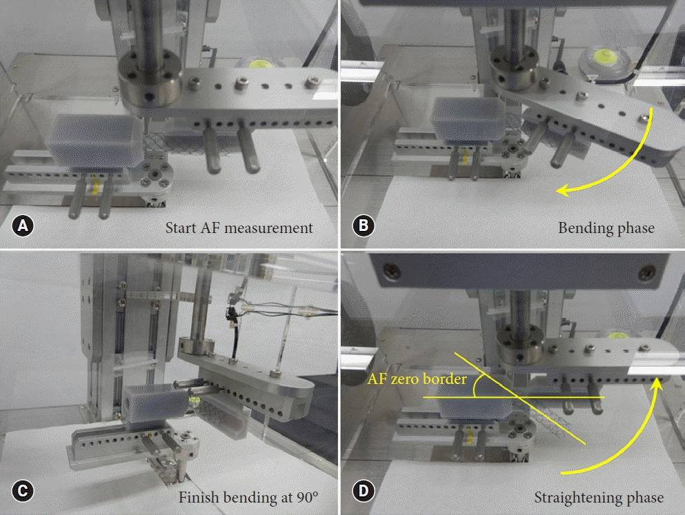
Axial force (AF) measurement method using the new device. (A) AF measurement at onset. (B) AF measurement during the bending phase. The yellow arrow in the photo indicates the direction in which the arm moves. (C) Transition from the bending to straightening phase at 90°. (D) AF measurement during the straightening phase. The axial force zero border was measured as the angle at which the torque force was <0.05 mNm during the straightening phase.
Statistical analysis
To compare the conventional and new measurement methods, a least squares linear regression analysis was performed using the IBM SPSS software ver. 24.0 (IBM Corp.). Statistical significance was set at p<0.05. The correlation strength was classified as excellent (correlation coefficient >0.7), good-to-excellent (0.6–0.7), good (0.4–0.6), or poor (<0.4).
Ethical statements
Not applicable.
RESULTS
Measurement of radial force
Figure 7 depicts the RF versus stent expansion-contraction curves for each type. All stents were classified according to their structure and cover status (present or absent). The graphs are similar for each stent in the various series (ComVi, Niti-S, and WallFlex). Figure 8 compares the RF versus stent expansion-contraction curves for all stents.

Radial force versus stent diameter curves. The same self-expandable metallic stents type, differing only in diameter, had similar curves. Expansion force was first measured using the cylinder until the stent was fully expanded. The diameter of the cylinder decreased, and the resistance force was measured (solid line: expansion force; dotted line: resistance force).

Radial force versus stent diameter curve for the ComVi, WallFlex, and Niti-S stents (solid line: expansion force; dotted line: resistance force).
All the stents had similarly shaped curves. The outward RF of all braided, covered SEMSs decreased rapidly at the beginning and end of the expansion phase. The forces of all braided, uncovered and laser-cut SEMSs decreased at the end of the expansion phase. The compression RF of all the SEMSs was stronger than the outward RF.
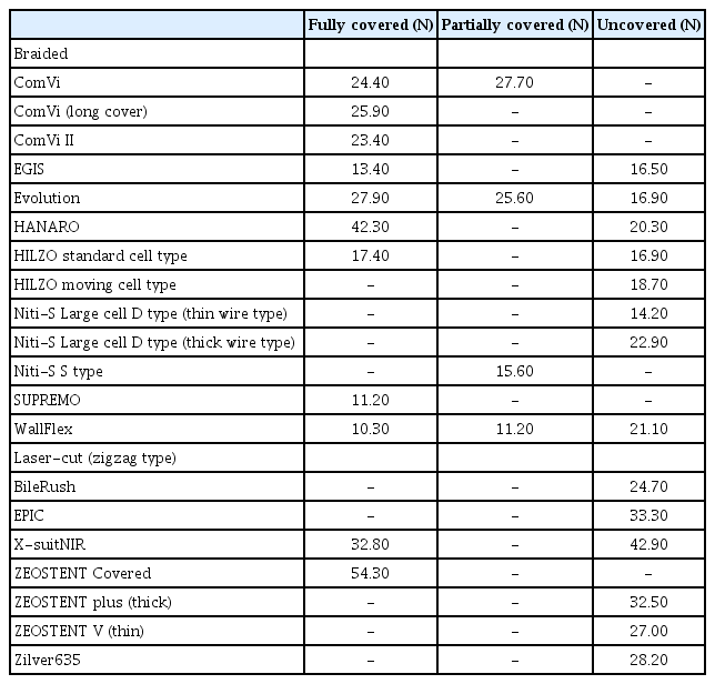
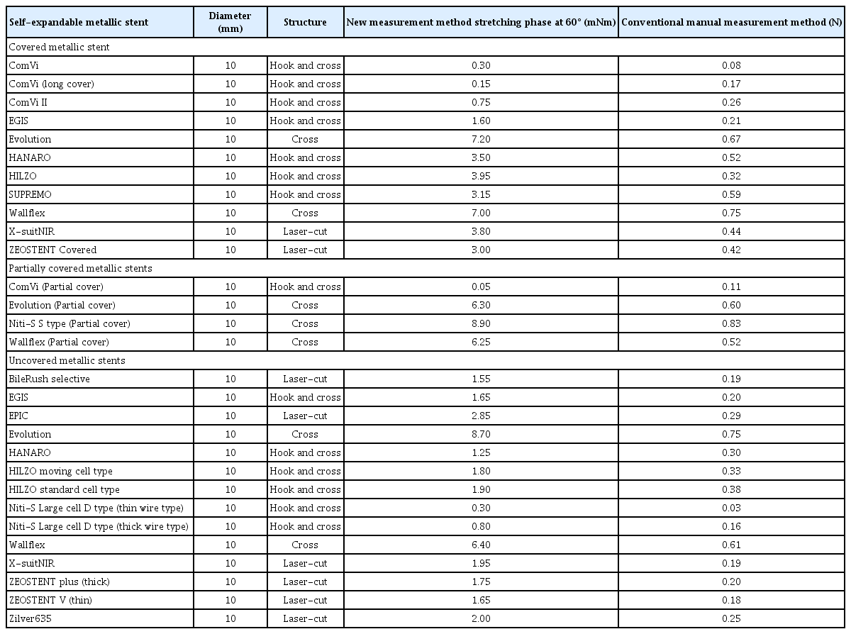
Table 3 lists the RF at a diameter of 4 mm during the expansion phase. The force of the braided SEMSs was generally <30 N, whereas that of the laser-cut SEMSs was >30 N.
Axial force measurement and comparison of the measurement methods
Table 4 lists the AF data obtained during the bending phase at 30°, 60°, and 90°, and at 60° during the straightening phase. These data were measured using the newly-developed AF measuring device. The AF at 60° during the straightening phase was compared among all the stents to evaluate the differences between the new and conventional measurement methods (Fig. 9 and Table 5). The AF measured by the two methods was highly correlated (y=9.2359x, R=0.9366, p<0.001).
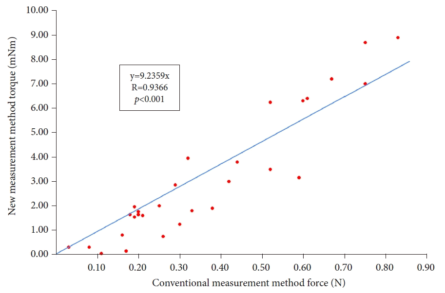
Axial force measured by the new and conventional methods; a strong correlation was found (y=9.2359x, R=0.9366, p<0.001).
Figure 10 depicts the AF versus ‘stent bending-straightening’ curves of each stent type, with SEMS classified by structure and cover status (present or absent). Figure 11 presents the AF versus ‘stent bending-straightening’ curves for each stent in the ComVi, Niti-S, and WallFlex series. The straightening AF was weaker than the resistance AF at the same angle. The forces on the covered SEMS were stronger than those on the uncovered SEMS.
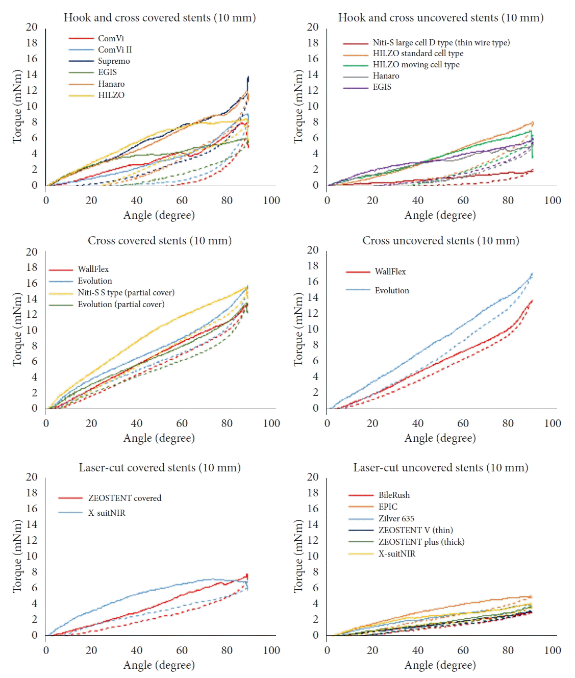
Axial force versus angle curves. The axial force of stents of various diameters was measured using the new measurement device. The stent was bent to 90° and then straightened (solid line: bending phase; dotted line: straightening phase).
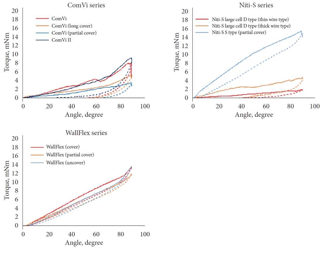
Axial force versus stent angle curves for ComVi, WallFlex, and Niti-S series stents (solid line: bending phase; dotted line: straightening phase).
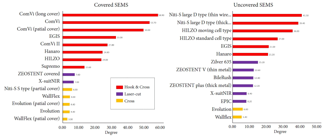
Table 4 lists the SEMS’s AFZB angles. Figure 12 shows that the AFZB angle was largest for the hook-and-cross-type stent, followed by the laser-cut- and cross-type stents. The hook-and-cross-type stent had an AFZB >20°, whereas that of the laser-cut- and cross-type stents were <20° for both the covered and uncovered stents. The AFZB of the ComVi series SEMSs was >50°.
Scatterplots of radial and axial force for all stents
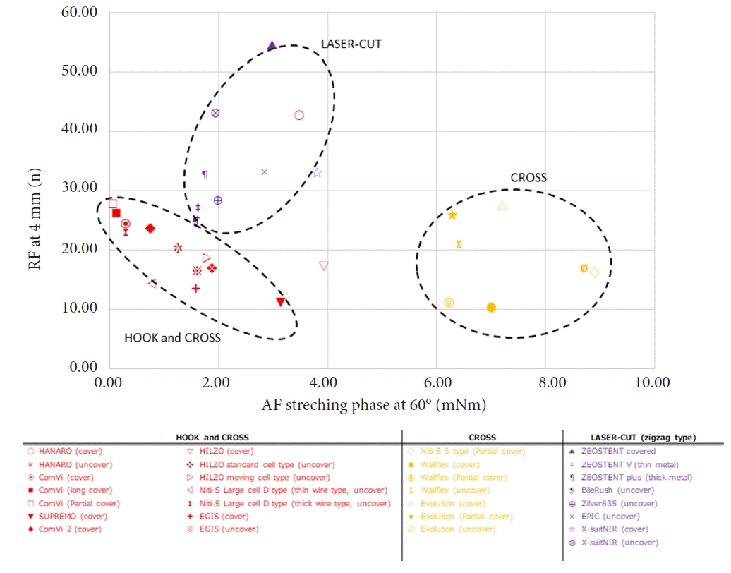
Figure 13 presents scatterplots of the outward RF at 4 mm and straightening RF at 60°, as measured by the new device. SEMs were classified according to their structure as laser-cut (zigzag-type), cross, and hook-and-cross types. The hook-and-cross-type had a low AF (0–3 mNm) and RF (10–30 N). The cross-type had a high AF (6–9 mNm) but low RF (10–30 N). The laser-cut-type had an intermediate AF (2–4 mNm) but a high RF (20–60 N). Thus, the stent structure had a stronger influence than the cover status on the RF and AF.
DISCUSSION
This is the second in vitro study to evaluate the MP (RF and AF) of biliary SEMSs.9 We changed the way AF is conventionally measured.17 In a previous report, the straightening AF was measured when the stent was bent at particular angles. In the present study, we employed a new newly-developed measurement device, where a force gauge inside the stent cylinder continuously recorded the straightening and resistance AF. The correlation between the AF data obtained using this new method and the conventional manual method was excellent (y=9.2359x, R=0.9366, p<0.001; Fig. 9).
There are two types of AF: the force applied when bending a straight stent (bending phase), and the force applied when straightening a bent state (straightening phase). The application of force to the bile duct wall after a stent is placed in the bile duct is clinically problematic; therefore, we compared the force when straightening from a bent condition, that is, the straightening AF. SEMS with high AF may not fit or could be unstable in the biliary duct, thus damaging the biliary wall and leading to the formation of sludge, cholangitis, and migration.5,9 Therefore, stents with excessive AF are not preferred. In this study, the cross-type stents had the strongest AF, followed by laser-cut, and hook-and-cross types. The influence of wire thickness, hook-to-cross ratio, and cover material on MP is difficult to assess because of the unique characteristics of and variability between stents (Table 2). The AF of the covered stents was higher than that of the uncovered stents when compared within the same series of hook-and-cross or laser-cut stents. The AF of the uncovered cross stents was almost the same as that of the covered cross stents (Table 4). Only the uncovered Evolution cross stent had a higher AF than the covered and partially covered cross stents. It is unclear why only this series exhibited the opposite trend, but this may be due to measurement errors or the unique weaving of the cover in this series. These results indicate that the primary determinant of stent AF is the stent structure, with cover status (present or absent) as a secondary factor.
AFZB is a new parameter proposed in the present study, which was precisely measured by continuous AF measurements using a newly-developed device. Stents with low AF had a high AFZB, and we observed a strong correlation between AF and AFZB (Table 4). This new parameter was defined as the angle at which the force applied to the biliary wall almost disappeared. Because no bile duct is completely straight, a SEMS with a very small AFZB angle could continuously compress and injure a part of the bile duct wall, resulting in ulceration, perforation, or bleeding. A SEMS with a large AF is more likely to cause stent-related complications, such as cholecystitis or pancreatitis, and the gap between the actual bend of the bile duct and AFZB may contribute to these complications. The relationship between AFZB and stent-related complications should be examined in the future.
There are two types of RFs: the force applied when the stent expands from the retracted state (outward RF) and the RF applied to resist stent contraction from the expanded state (compression RF). The force (outward RF) at which the stent dilates the stenosis is clinically important, and was thus evaluated. The RF of the covered SEMSs decreased rapidly at the beginning of the expansion phase (Fig. 7). We assumed that the crossover wire and cover membranes may have created a friction during the initial expansion motion, thereby increasing the RF value. We observed less friction at the beginning of an uncovered SEMS opening; this phenomenon has been previously reported, and the friction was lower than that in previous SEMSs.17
We categorized the 10-mm SEMSs into three subgroups according to stent structure (Fig. 13): the hook-and-cross group had a low AF (0–3 mNm) and RF (10–30 N); the cross group had a high AF (6–9 mNm) but low RF (10–30 N); and the laser-cut group had an intermediate AF (2–4 mNm) but a high RF (20–60 N). These MP are useful in selecting the best SEMS for a given case.18 Based on our experience and previous reports, RF influences migration,16,19 and AF is related to bile duct kinking,11,20,21 pancreatitis,14 and cholecystitis12 due to compression of the bile duct, cystic duct orifice, or pancreatic orifice. Therefore, the ideal SEMSs are those with high RF and low AF. When selecting the ideal SEMS for an individual case based on AFZB, we recommend using stents with a high RF rather than those with an AFZB below the angle of bile duct bend because the AF is theoretically zero if the angle of the bile duct is below the AFZB.
This study had several limitations. First, we could not evaluate all the SEMS available in Japan or other countries. A standard AF measurement method would facilitate larger studies including more stent types. Second, no standard AF measurement method has been established, and the instrument used in this study is not widely available. Currently, we are developing a commercially available AF measurement instrument. Third, we could not measure the MP of each part of the SEMS body or special parts, such as flares.
In conclusion, we examined the MP of several SEMSs using a new AF measurement method and proposed a new measurement parameter: the angle at which the AF disappears (AFZB). Hook-and-cross-type SEMSs had a low AF and high AFZB and were considered safe because they exerted minimal stress on the biliary wall. However, the increase in RF must be overcome.
Notes
Conflicts of Interest
T.F. received a personal fee from Boston Scientific, Japan. T.S. received a personal fee from Boston Scientific Japan, Century Medical Inc., Cook Japan, and SB-KAWASUMI Laboratories, Inc. S.Y. received personal fees from Boston Scientific Japan and consultant fees from Olympus Medical Systems Corp. S.N. and K.I. are researchers working at Zeon Corporation. Y.N. received grants from Boston Scientific Japan, Century Medical Inc., and Zeon Medical Inc. and received a personal fee from Boston Scientific Japan, Century Medical Inc., and Olympus Medical Systems Corp. N.S. received personal fees from Boston Scientific, Japan. H.I. received grants from Boston Scientific Japan, Zeon Medical Inc., and Century Medical Inc., and a personal fee from Boston Scientific Japan, Japan Lifeline Co., Ltd., Zeon Medical Inc., Century Medical Inc., Olympus Medical System Corp., Taewoong Medical Co., Ltd., Create Medic Co. Ltd., and Cook Japan. W.Y., R.I., and T.S. have no conflicts of interest or financial ties to disclose.
Funding
None.
Acknowledgments
This in vitro study was conducted at the Medical Laboratory, Research and Development Center, Zeon Corporation, Toyama, Japan. We thank the Zeon Corporation for access to the measurement system used in this study. The staff of Zeon Medical Inc. and Zeon Corporation (Nobukazu Nishimura, Tetsuji Shimono, Takuya Kagoshima, Atsushi Yasunaka, Koichi Inoue, Kou Kayukawa, Hiromi Mizoroki, Hiroki Shinagawa, and Chimyon Gon) supported this study (the data interpretation and preparation of this paper were performed by doctors). We also express our sincere appreciation to the manufacturers and distributors for providing the SEMSs used in this study, including BCM Co. Ltd, Boston Scientific Corporation, Century Medical Inc., Cook Medical, M.I. TECH. Co. Ltd., Olympus Medical Systems, Piolax Inc., S&G Biotech Inc., Sumitomo Bakelite Co. Ltd., Taewoong Medical Co. Ltd., and Zeon Medical Inc.
Author Contributions
Conceptualization: YN, NS, HI; Data curation: TF, TaS, RI, ToS, SY; Formal analysis: WY, TF; Supervision: HI; Validation: KI, SN; Visualization: TaS, RI, ToS, SY; Writing–original draft: YW, TF, HI; Writing–review & editing: TF, TaS, RI, ToS, SY, KI, SN, YN, NS, HI.

